Parametrica is a new generation tool, created for true art of engineering. This product is an enhancement of the 3D browser and enables to create complex parametric models which can be later used for 3D printing, optimization in computer-aided engineering (CAE) applications and in other cases where capabilities of CAD systems are not sufficient
All pictures on this page are made in Flypoint 3D Browser. The application displays models written in a new virtual reality markup language FLYP, and supports their interactivity. Flypoint is as easy to use as usual HTML browsers, but websites in it are more similar to 3D games
You can order the development of interactive parametric 3D models from us. Each such model is a generator of a whole family of products and the basis for selecting the best option. Together with the models you will receive Flypoint Parametrica for free, which will save you from designing in CAD, or greatly simplify it
Gallery
The interactive parametric model of the hydrofoil for the Olympic discipline "Kitesurfing" was chosen as a demonstration of the capabilities of the models created using the FLYP language. The designer can give the product any appearance by moving the mouse for user-friendly hot points, print a suitable option on a 3D printer, or send it for calculation to clarify. In this video, you can get acquainted with the parametric model of the hydrofoil
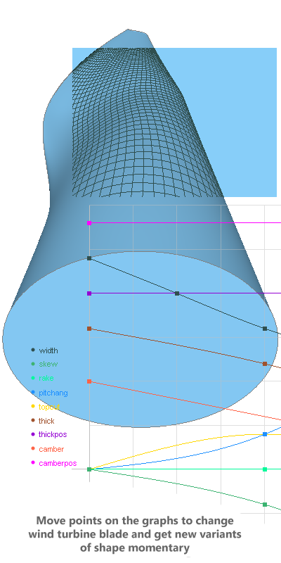
Flypoint Software has completed a full design cycle for a wind turbine blade including unique 3D optimization. Our blades have been made and presented at the St. Petersburg International Economic Forum 2019. An important aspect of this work was that at all stages, from design to manufacturing, only Flypoint Parametrica was used. The principle "from parameters to the product in a few clicks" was introduced, including integration with the Siemens Star CCM+ solver and the external optimizer Datadvance pSeven. The animation shows the process of selecting the top edge shape important for a wind turbine
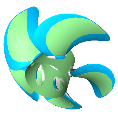
A marine propeller is a complex surface, for which it is necessary to perform the operation of smooth joining to the hub, which brings the modeling of propellers to the top of the high technology. If you use CAD, then the designer needs to do tremendous manual work. However, serious design requires more - for example, manipulating a transition fillet, or generating propellers automatically. We do this - on the video you can learn more about the capabilities of marine propeller models in Flypoint Parametrica
The picture shows a sail from real practice. If you make an effort, you can draw such a sail in CAD, but you can never deform it correctly – as it is shown in the animation. This deformation is caused by a change in wind strength or a tuning of the sail. Obviously, for computer-aided design of sails, it is necessary to obtain a form using natural deformation. The secret of managing complex smooth forms is the organization of control parameters in the form of curves. Flypoint can do this and the animation shows how you can control the sail using curves
This New Year's forest was made on the basis of only one Christmas tree. All other trees were derived using the array reproduction technology. A simple deformation was applied to each element of the array and a style was selected. This made it possible to set only 4 parameters to control the lushness of the forest, which can be changed with a light mouse movement up and down (such controls are created by means of FLYP without programming). Additionally, all Christmas baubles on every tree are also obtained as the array elements
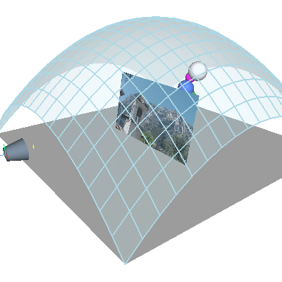
In this experiment, a complex spline surface, described by 144 points, is controlled by only 9 hot points. In the animated picture, the user moves the central hot points down with the mouse and gets the desired result. Such an effect became possible due to the use of the Free Form Deformation technology on the base layer of the Flypoint geometric kernel. This model, like everything presented here, is written completely in the FLYP modeling language
In order for the user to set the minimum number of parameters to control the model, he needs to have a large selection of tools. For example, one of such tools is sharing one element in different parts of the model. In this experiment, a circle is used as an opening for two different planes. To change the radius at the same time for all holes, it is enough to change only one parameter - the radius of the circle common to all. In addition, FLYP allows you to make common also other parameters, such as the position of the circle. The animated picture also shows how Flypoint geometric kernel rebuilds the mesh